-
-
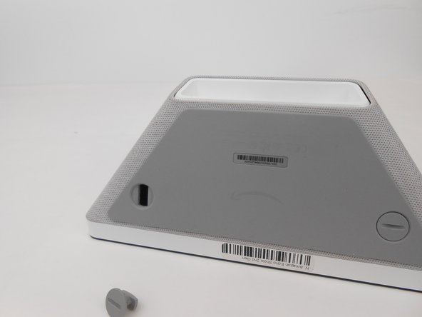
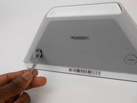
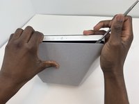
Turn the two screw plugs counterclockwise with a metal spudger until they are 90 degrees from their original position.
-
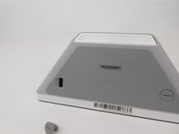
Pull each of the plugs out.
-
-
-
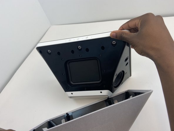
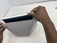
Use the metal spudger to pry and create space between the sound foam and the frame.
-
Once you have sufficiently pried the foam from the frame on each side, detach the sound foam from the frame with your hands.
-
-
-
Turn the two screw plugs counterclockwise with a metal spudger until they are 90 degrees from their original position
-
Pull each of the plugs out
-
-
-
-
Use the metal spudger to pry and create space between the sound foam and the frame
-
Once you have sufficiently pried the foam from the frame on each side, detach the sound foam from the frame with your hands.
-
-
-
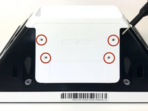
Unscrew the white case using the TR1 screwdriver bit to remove the 4mm screws.
-
Pull on top of case until it becomes dislodged
-
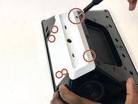
Unscrew the two Torx T8 screws below the sound card
-
-
-
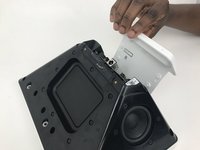
Remove the bracket holding in the orange connector to the sound card and unplug it.
-
Unscrew the screw from the black ground cable.
-
-
-
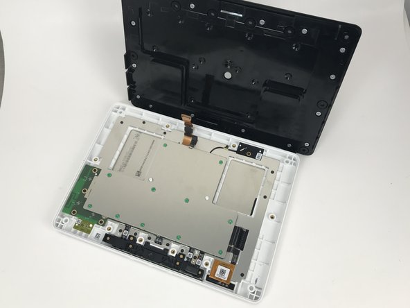
Unscrew the remaining 6 T8 Torx screws from the top and sides of the device
-
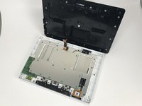
Once all the T8 Torx screws are unscrewed, the speaker assembly should be very easy to remove.
-
-
-
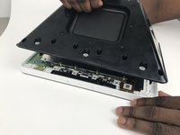
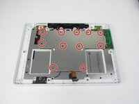
Remove all the 4mm length screws in the indicated areas using a TR6 torque screwdriver.
-
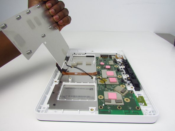
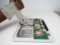
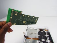
To reveal the motherboard of the device, gently pry off the metal plate away from the rest of the device.
-
-
-
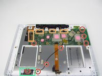
Remove all 8 of the 4 mm screws from the indicated areas using the TR6 screwdriver.
-
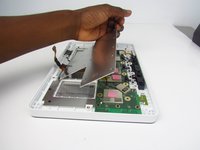
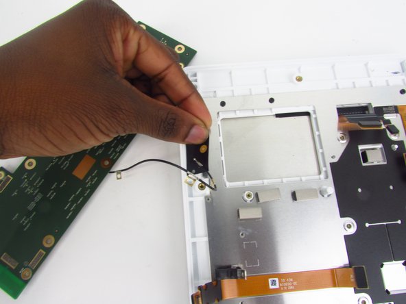
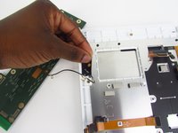
Using your hands, gently detach the connected areas from the motherboard. To do so, simply pry the adhesives off with your fingers.
-
Carefully detach the adhesive. Make sure the wire attached to the adhesive stays attached when removing the motherboard. To do so, gently hold the wire in place.
-


To reassemble your device, follow these instructions in reverse order.
crwdns2935221:0crwdne2935221:0
crwdns2935229:02crwdne2935229:0

crwdns2935287:0crwdne2935287:0

Embry-Riddle Aeronautical University, Team S3-G2, Watkins Spring 2020 crwdns2935289:0Embry-Riddle Aeronautical University, Team S3-G2, Watkins Spring 2020crwdne2935289:0
ERAU-WATKINS-S20S3G2
crwdns2931471:04crwdne2931471:0
crwdns2935297:05crwdne2935297:0
crwdns2947410:01crwdne2947410:0
These instructions are missing one important step, at least on my version of the Echo Show 10 2nd gen. There are 8 Tr8 screws holding the big black backside with the speakers + sound card in place 4 at the top, 2 on each side and 2 at the bottom.
These 8 screws need to be removed before separating the back from the front in Step 3 of this guide.
To get to the 2 screws at the bottom the white cover which covers the sound-card and the connectors on the back needs to be removed as is described in the Sound Card replacement guide. Note the white cover is not only attached with 6 tr1 screws there also is some double-sided tape holding it in place at the edge near the power-connector you can see the tape remains at the first Picture of step 3 of the Sound Card replacement guide.
Since the white cover needs to be removed anyways it is easier to remove the cables to the sound card on the sound card side, as is shown in step 5 of the Sound Card replacement guide.