crwdns2933423:0crwdne2933423:0

AirPort Extreme A1521 Logic Board Replacement

crwdns2942213:0crwdne2942213:0

  1. AirPort Extreme A1521 Logic Board Replacement, Internal Structure: crwdns2935265:01crwdnd2935265:01crwdnd2935265:02crwdne2935265:0 AirPort Extreme A1521 Logic Board Replacement, Internal Structure: crwdns2935265:01crwdnd2935265:02crwdnd2935265:02crwdne2935265:0
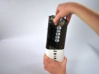
    • Using a metal spudger, gently pry the cover off the bottom of the device.

  2. AirPort Extreme A1521 Logic Board Replacement: crwdns2935265:02crwdnd2935265:01crwdnd2935265:02crwdne2935265:0 AirPort Extreme A1521 Logic Board Replacement: crwdns2935265:02crwdnd2935265:02crwdnd2935265:02crwdne2935265:0
    • Four black internal wires, three thin and one thick, are connected to the logic board: three by small end clips and one by a larger end clip. Handle the clips gently; they break easily.

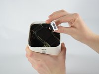
    • To detach the small clips from the connectors, place the flat end of the plastic spudger underneath the clip and gently lever it away from the center of the device.

    • To detach the large clip from its connector, place the flat end of the spudger on the clip and lever it upward out of the connector.

  3. AirPort Extreme A1521 Logic Board Replacement: crwdns2935265:03crwdnd2935265:01crwdnd2935265:03crwdne2935265:0 AirPort Extreme A1521 Logic Board Replacement: crwdns2935265:03crwdnd2935265:02crwdnd2935265:03crwdne2935265:0 AirPort Extreme A1521 Logic Board Replacement: crwdns2935265:03crwdnd2935265:03crwdnd2935265:03crwdne2935265:0
    • Using two fingers, pinch the power supply wire and gently lift it upward. Move it away from the metal plate.

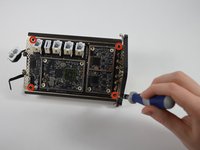
    • Next, unscrew the four 3.3mm T8 Torx screws and remove the metal plate.

    • The metal plate fits snugly into the gap. To reassemble the device, push the rounded edge of the plate into the gap first. This will wedge the gap open so that you can fit the rest of the plate into its proper place.

  4. AirPort Extreme A1521 Logic Board Replacement: crwdns2935265:04crwdnd2935265:01crwdnd2935265:01crwdne2935265:0
    • Remove the T8 Torx screwdriver head and replace it with the 60 mm extension; then, add the T9 Torx head.

    • Loosen, but do not remove the two screws at the bottom of the 1.2-inch wide gap in the middle of the internal structure.

    • These screws are spring-loaded and will stay in the device, even when loosened; however, it is still possible for them to be fully removed. Be careful to only partially loosen them.

  5. AirPort Extreme A1521 Logic Board Replacement: crwdns2935265:05crwdnd2935265:01crwdnd2935265:02crwdne2935265:0 AirPort Extreme A1521 Logic Board Replacement: crwdns2935265:05crwdnd2935265:02crwdnd2935265:02crwdne2935265:0
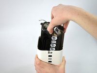
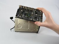
    • Using only your fingers, gently compress the internal structure and pull evenly upward to remove it from the white case.

    • When you put the internal structure back into the case, gently compress it, and lower it most of the way into the case. Stop lowering it when the top port has just entered the case. Now push the two sides of the internal structure outward against the sides of the case.

    • Finish lowering the internal structure the rest of the way into the case. The ports should be lined up with the openings in the case and should be flush against the sides of the case.

  6. AirPort Extreme A1521 Logic Board Replacement, Logic Board: crwdns2935265:06crwdnd2935265:01crwdnd2935265:01crwdne2935265:0
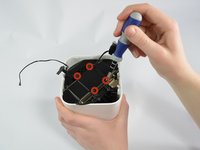
    • Eight 10.25 mm T8 Torx screws secure the heat sink to the logic board. Unscrew all eight screws.

    • Remove the heat sinks from the logic board.

  7. AirPort Extreme A1521 Logic Board Replacement: crwdns2935265:07crwdnd2935265:01crwdnd2935265:01crwdne2935265:0
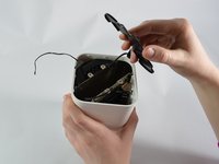
    • Wedge the corner of the plastic spudger under one of the silver antenna clips. Gently lever the tip of the spudger away from the logic board to detach the antenna clip.

    • Repeat this for all six clips.

  8. AirPort Extreme A1521 Logic Board Replacement: crwdns2935265:08crwdnd2935265:01crwdnd2935265:02crwdne2935265:0 AirPort Extreme A1521 Logic Board Replacement: crwdns2935265:08crwdnd2935265:02crwdnd2935265:02crwdne2935265:0
    • To release the logic board, unscrew four 5.5 mm T8 Torx screws from the internal structure.

    • Remove the logic board from the internal structure.

crwdns2915888:0crwdne2915888:0

To reassemble your device, follow these instructions in reverse order.

crwdns2935229:05crwdne2935229:0

Keith Yu

crwdns2935283:010/18/13crwdne2935283:0

829 crwdns2915208:0crwdne2915208:0

crwdns2935297:02crwdne2935297:0

crwdns2915084:0crwdne2915084:0

Cal Poly, Team 4-26, Amido Fall 2013 crwdns2935289:0Cal Poly, Team 4-26, Amido Fall 2013crwdne2935289:0

CPSU-AMIDO-F13S4G26

crwdns2931471:05crwdne2931471:0

crwdns2935297:018crwdne2935297:0

crwdns2944067:02crwdne2944067:0

Nice teardown but where can you buy a replacement logic board?

mediamixsound - crwdns2934203:0crwdne2934203:0

Hi everyone! Can someone provide a more closer picture of the 2 connectors that goes to the fan and to led. I accidentally broke those 2 small connectors and i was trying to solder them back. A more closer picture of the zone would help me a lot.

Sebastian Cancel - crwdns2934203:0crwdne2934203:0

crwdns2917038:0crwdne2917038:0

crwdns2936625:0crwdne2936625:0:

crwdns2936751:024crwdne2936751:0 1

crwdns2936753:07crwdne2936753:0 10

crwdns2936753:030crwdne2936753:0 28

crwdns2942667:0crwdne2942667:0 11,435