crwdns2915892:0crwdne2915892:0
Whether your Acer TravelMate P653-V-6882 begins to overheat, you need to access the I/O ports, or replace the LCD module, then you must remove the mainboard, also known as the motherboard.
Here is a guide on how to access the TravelMate’s mainboard (motherboard), where you then can begin to either remove it and fix any issues you are facing with the internals.
crwdns2942213:0crwdne2942213:0
-
-
Turn the computer over so the base is facing up.
-
Slide the battery lock to unlock position.
-
-
-
Slide the battery release latch to the right.
-
-
-
Lift the battery up.
-
Pull out the battery.
-
-
-
Slide the ODD module latch down.
-
-
-
Remove the five 7mm Phillips #1 screws.
-
-
-
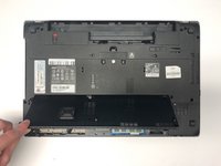
Use the opening tool to separate base door from the bottom of the laptop.
-
-
-
Gently pry open the base door by pushing up.
-
Pull out the base door.
-
-
-
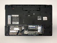
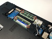
Locate the two RAM sticks on the bottom of the laptop.
-
-
-
-
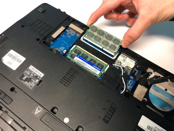
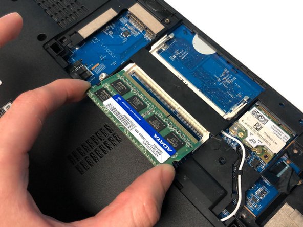
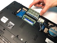
Pinch the two metal pieces holding the RAM sticks in place outwards.
-
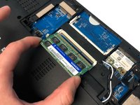
Holding the sides of the RAM, slide the RAM sticks out.
-
-
-
Remove the two 7mm Phillips #1 screws.
-
-
-
Flip the laptop so that the underside is now facing the bottom.
-
Open the LCD panel.
-
Use the flat end of a spudger to push in the six latches.
-
-
-
When the latches are pushed in, the keyboard will pop out.
-
Gently pry up the keyboard.
-
-
-
Slide the keyboard forward to access the keyboard cable.
-
Flip the connector latch up to open it.
-
Pull out the keyboard cable gently.
-
-
-
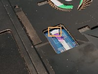
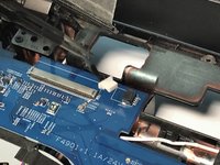
Turn the computer over, open the LCD panel, and find the smart card cable connector.
-
Open the smart card cable connector latch.
-
Disconnect the cable.
-
-
-
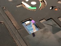
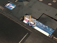
Find the power button launch board cable connector.
-
Open the power button launch board cable connector latch.
-
Disconnect the cable.
-
-
-
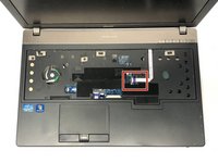
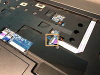
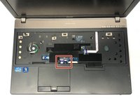
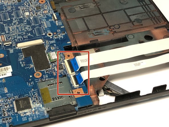
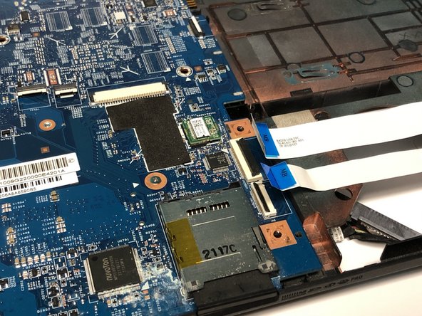
Find the touchpad and fingerprint board cable connector.
-
Open the touchpad and fingerprint board cable connector’s latches.
-
Disconnect the cables.
-
-
-
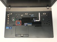
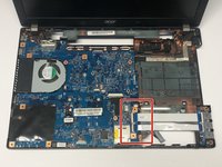
Using the #1 Phillips screwdriver, remove the two screws.
-
-
-
Flip the laptop over so that the underside is facing up.
-
Remove the twelve 7mm Phillips #1 screws.
-
Remove the five 3mm Phillips #1 screws.
-
Disconnect the cables connecting to the WLAN module.
-
-
-
Flip the laptop so that the underside is now facing the bottom.
-
Open the LCD panel.
-
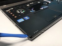
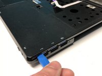
Locate the small gaps between the upper cover and lower case on the left and right side of the laptop.
-
Insert the opening tool into each gap to separate the one from the other.
-
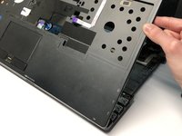
Once the upper cover is separated, lift it from the lower case.
-
-
-
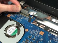
Detach the transparent tape securing the LCD cable.
-
Disconnect the LCD cable from the mainboard.
-
-
-
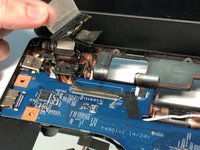
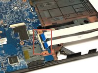
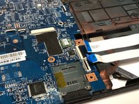
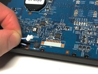
Detach the black tape covering the microphone cable.
-
Disconnect the microphone cable from the mainboard.
-
-
-
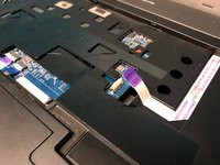
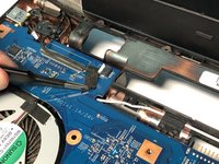
Open the USB board cable's connector latches.
-
Disconnect the cables.
-
-
-
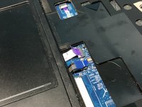
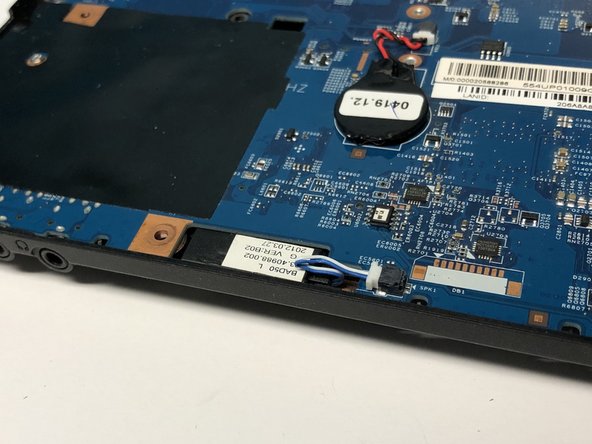
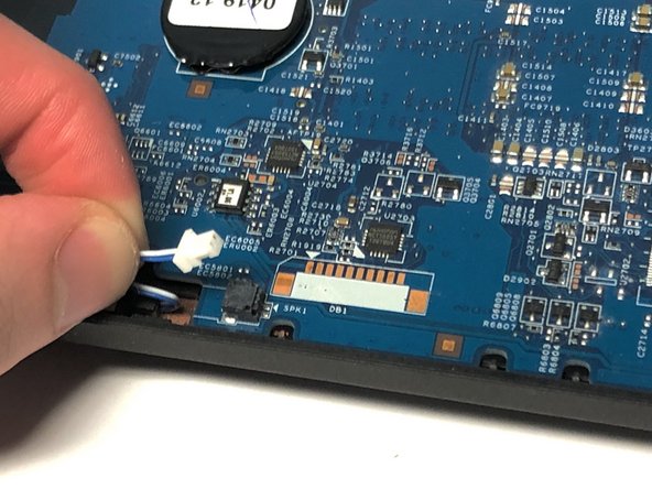
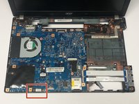
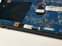
Disconnect the left speaker cable from the mainboard.
-
-
-
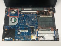
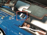
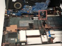
Remove the one 7mm Phillips #1 screw.
-
-
-
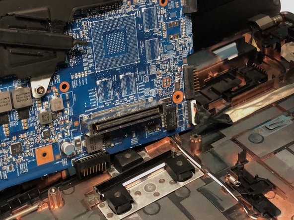
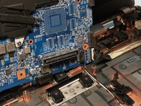
Lift the mainboard at an angle and gently turn it on its side.
-
Disconnect the LAN cable from the mainboard.
-


To reassemble your device, follow these instructions in reverse order.
To reassemble your device, follow these instructions in reverse order.
crwdns2935221:0crwdne2935221:0
crwdns2935227:0crwdne2935227:0
crwdns2915084:0crwdne2915084:0

York University, Team S1-G6, Woodhouse Winter 2020 crwdns2935289:0York University, Team S1-G6, Woodhouse Winter 2020crwdne2935289:0
YORK-WOODHOUSE-W20S1G6
crwdns2931471:03crwdne2931471:0
crwdns2935297:09crwdne2935297:0