crwdns2915892:0crwdne2915892:0
Dropping your laptop, on multiple occasions, increases the chance of the display to stop functioning. If you’re facing this issue and your TravelMate’s display does not light up after troubleshooting, the display may likely be damaged. This means that you will need to replace the LCD module.
Here is a guide on how to replace the Acer TravelMate P653-V-6882's LCD module. It is important to know that when you are replacing the LCD module, you must do a complete teardown of the device.
crwdns2942213:0crwdne2942213:0
-
-
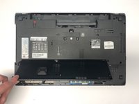
Turn the computer over so the base is facing up.
-
Slide the battery lock to unlock position.
-
-
-
Slide the battery release latch to the right.
-
-
-
Lift the battery up.
-
Pull out the battery.
-
-
-
Slide the ODD module latch down.
-
-
-
Remove the five 7mm Phillips #1 screws.
-
-
-
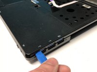
Use the opening tool to separate base door from the bottom of the laptop.
-
-
-
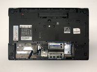
Gently pry open the base door by pushing up.
-
Pull out the base door.
-
-
-
Remove the two 7mm Phillips #1 screws.
-
-
-
Flip the laptop so that the underside is now facing the bottom.
-
Open the LCD panel.
-
Use the flat end of a spudger to push in the six latches.
-
-
-
-
When the latches are pushed in, the keyboard will pop out.
-
Gently pry up the keyboard.
-
-
-
Slide the keyboard forward to access the keyboard cable.
-
Flip the connector latch up to open it.
-
Pull out the keyboard cable gently.
-
-
-
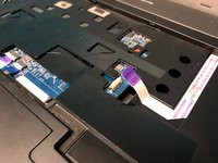
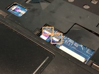
Turn the computer over, open the LCD panel, and find the smart card cable connector.
-
Open the smart card cable connector latch.
-
Disconnect the cable.
-
-
-
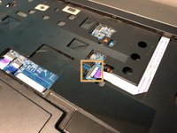
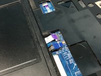
Find the power button launch board cable connector.
-
Open the power button launch board cable connector latch.
-
Disconnect the cable.
-
-
-
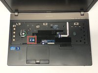
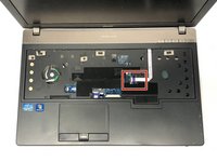
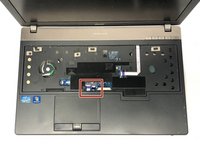
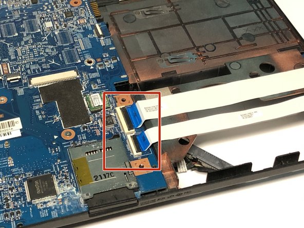
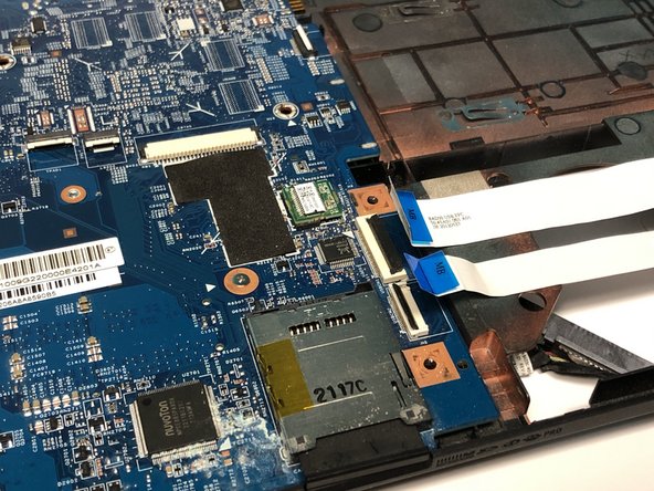
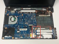
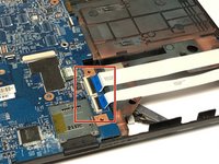
Find the touchpad and fingerprint board cable connector.
-
Open the touchpad and fingerprint board cable connector’s latches.
-
Disconnect the cables.
-
-
-
Using the #1 Phillips screwdriver, remove the two screws.
-
-
-
Flip the laptop over so that the underside is facing up.
-
Remove the twelve 7mm Phillips #1 screws.
-
Remove the five 3mm Phillips #1 screws.
-
Disconnect the cables connecting to the WLAN module.
-
-
-
Flip the laptop so that the underside is now facing the bottom.
-
Open the LCD panel.
-
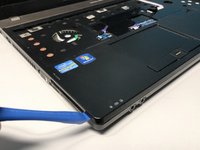
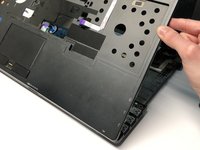
Locate the small gaps between the upper cover and lower case on the left and right side of the laptop.
-
Insert the opening tool into each gap to separate the one from the other.
-
Once the upper cover is separated, lift it from the lower case.
-
-
-
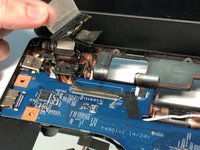
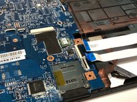
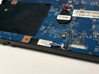
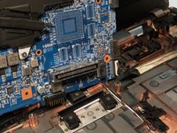
Detach the transparent tape securing the LCD cable.
-
Disconnect the LCD cable from the mainboard.
-
-
-
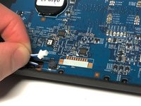
Detach the black tape covering the microphone cable.
-
Disconnect the microphone cable from the mainboard.
-
-
-
Open the USB board cable's connector latches.
-
Disconnect the cables.
-
-
-
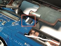
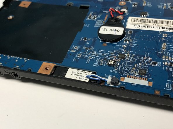
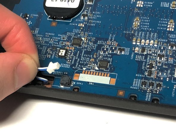
Disconnect the left speaker cable from the mainboard.
-
-
-
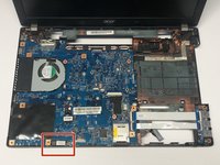
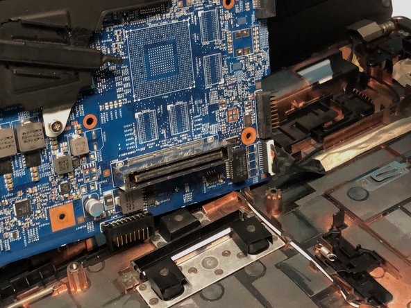
Remove the one 7mm Phillips #1 screw.
-
-
-
Lift the mainboard at an angle and gently turn it on its side.
-
Disconnect the LAN cable from the mainboard.
-
-
crwdns2935267:0crwdne2935267:0Tweezers$4.99
-
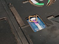
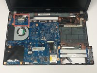
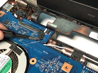
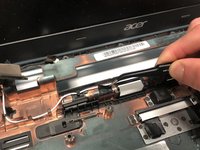
Carefully remove the two pieces of black tape securing the antenna cables to the lower case using tweezers.
-
-
-
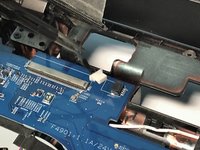
Release the white antenna cable from its top side latches.
-
-
-
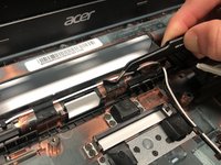
Release the black antenna cable from its top side latches.
-
-
-
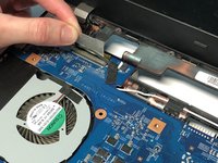
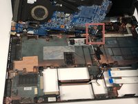
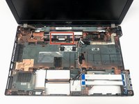
Remove the two 7mm Phillips #1 screws.
-
-
-
Carefully remove the LCD module from the lower case.
-


To reassemble your device, follow these instructions in reverse order.
To reassemble your device, follow these instructions in reverse order.
crwdns2915084:0crwdne2915084:0

York University, Team S1-G6, Woodhouse Winter 2020 crwdns2935289:0York University, Team S1-G6, Woodhouse Winter 2020crwdne2935289:0
YORK-WOODHOUSE-W20S1G6
crwdns2931471:03crwdne2931471:0
crwdns2935297:09crwdne2935297:0