crwdns2915892:0crwdne2915892:0
If your Acer Spin 5 SP515-51GN-807G has stopped working due to a motherboard failure (usually as a result of water or impact damage), use this guide to replace the motherboard unit.
The motherboard is the main circuit board of a computer that allows communication between many of the crucial electronic components of the system, such as the processor (CPU), memory (RAM), and storage (SSD or HDD). If the motherboard has failed in any way, the computer will likely not function. However, it is possible that the computer could still power on showing a blue or black screen with a damaged motherboard.
Prior to using this guide, use our Back Cover Removal Guide to get a better look at the motherboard unit and inspect for damage. If damage is found to the motherboard (commonly liquid or impact), then proceed to motherboard replacement guide below.
Although tedious in nature due to the many disconnections that must be made to remove the motherboard, this guide does not require any advanced technical skills to complete. Additionally, no soldering or electrical work is necessary.
Before beginning, make sure you power off the device completely and complete the two (2) prerequisite guides listed below.
crwdns2942213:0crwdne2942213:0
-
-
Remove the eleven 6.5 mm screws that secure the back case using a Phillips #1 screwdriver.
-
-
-
Use a plastic opening tool to gently pry open the back cover.
-
-
-
Gently remove the back cover from the device.
-
-
crwdns2935267:0crwdne2935267:0Tweezers$4.99
-
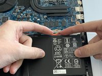
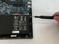
Using tweezers, remove the piece of black tape over the battery cable connector.
-
-
-
Remove the piece of black tape that covers the battery.
-
-
-
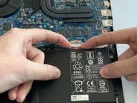
Grip the battery cable on both sides with your fingertips and gently pull it away from the port.
-
-
-
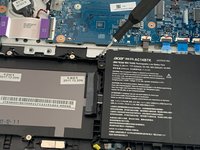
Remove the two 3.5 mm screws that secure the battery using a Phillips #00 screwdriver (PH00 bit).
-
-
-
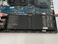
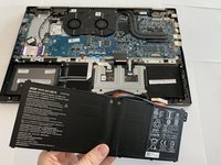
Carefully place your fingers under the plastic lip where the screws were removed.
-
Lift upwards to remove the battery.
-
-
crwdns2935267:0crwdne2935267:0Tweezers$4.99
-
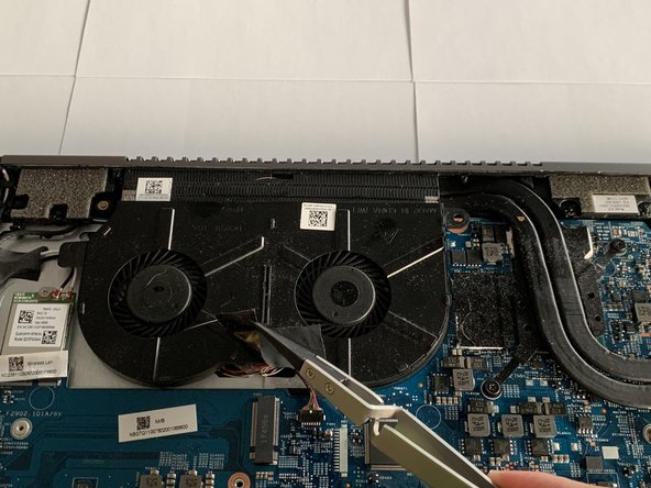
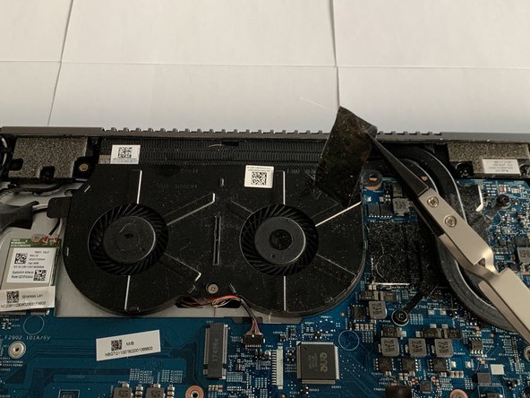
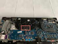
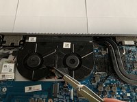
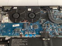
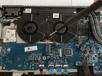
Remove the piece of tape covering the fan screw using a pair of tweezers.
-
-
-
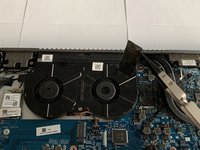
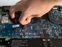
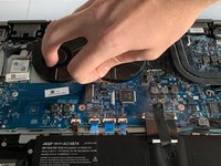
Grip the cord that connects the fan to the motherboard and gently pull out to disconnect the cable from the connector.
-
-
-
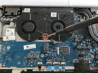
Remove the 3.5 mm screw connecting the fan to the computer using a Phillips #00 screwdriver (PH00 bit).
-
-
-
-
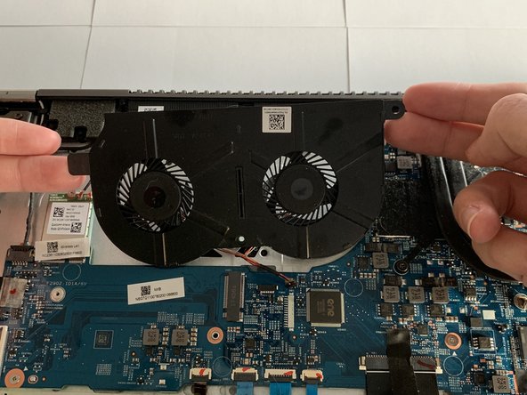
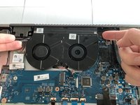
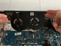
Grip the fan with your fingers by the edges and lift up to remove the fan.
-
-
-
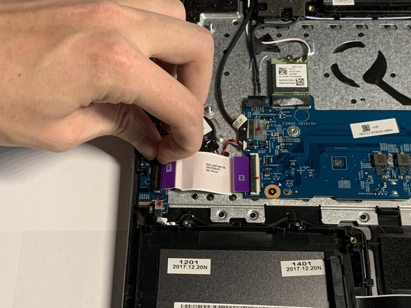
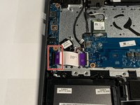
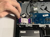
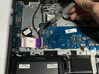
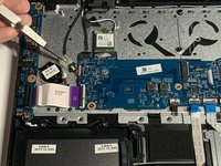
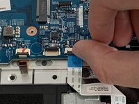
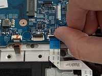
Place your fingernail underneath the locking tab of the ZIF connector holding the interconnect cable on the USB/Side Port board.
-
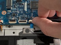
Lift the black clamp upwards to release the cable.
-
-
-
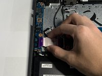
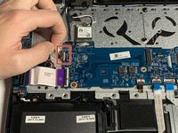
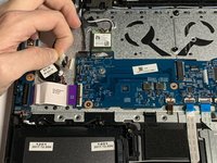
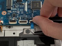
Pull the USB/Side Port Board cable away from the port.
-
-
-
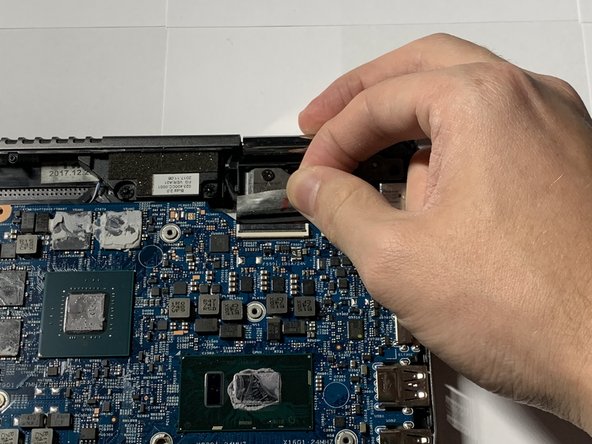
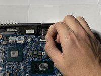
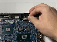
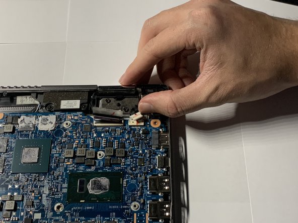
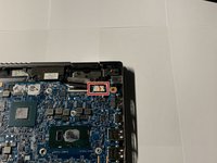
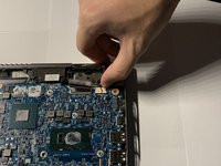
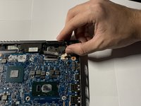
Firmly grasp the cable that connects the speakers to the motherboard.
-
Gently pull the cable away from the motherboard.
-
-
crwdns2935267:0crwdne2935267:0Tweezers$4.99
-
Peel back the tape covering the cable port.
-
-
-
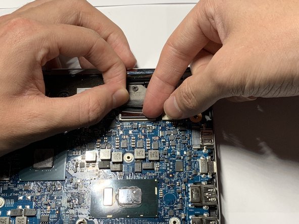
Firmly grasp the cable.
-
Gently pull the cable away from the motherboard.
-
-
-
Firmly grasp the cable.
-
Gently pull the cable away from the motherboard.
-
-
-
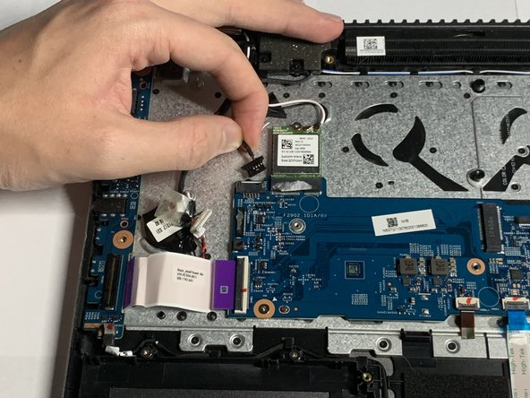
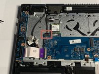
Remove the one 3.5mm screw that secures the wireless card using a Phillips #00 screwdriver (PH00 bit).
-
-
-
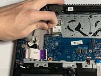
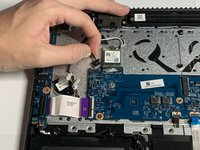
Gently pull the wireless card away from the motherboard.
-
-
-
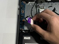
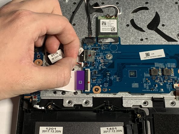
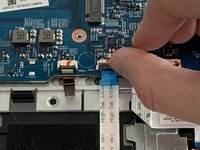
Place your fingernail underneath the black tab which secures the cable in the ZIF connector.
-
Lift the black tab upwards to release the cable.
-
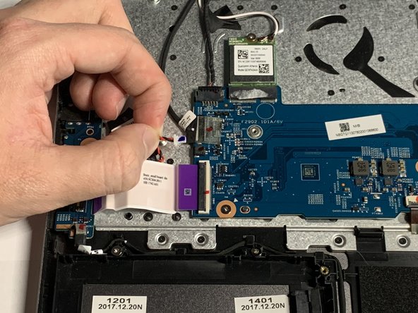
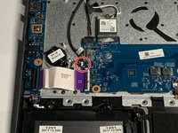
Gently pull the cable away from the motherboard.
-
-
-
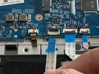
Place your fingernail underneath the black tab which secures the cable in the ZIF connector.
-
Lift the black tab upwards to release the cable.
-
Gently pull the cable away from the motherboard.
-
-
-
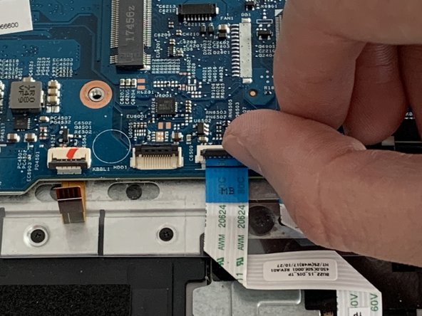
Place your fingernail underneath the black clamp which secures the cable.
-
Lift the black clamp upwards to release the cable.
-
Gently pull the cable away from the motherboard.
-
-
-
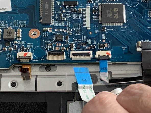
Place your fingernail underneath the black clamp which secures the cable.
-
Lift the black clamp upwards to release the cable.
-
Gently pull the cable away from the motherboard.
-
-
-
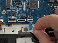
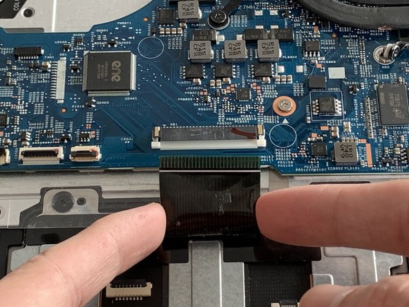
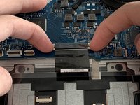
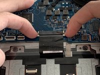
Grip the two white clamps on each side of the cable with your fingernails and pull away from the motherboard to release the cable.
-
Gently pull the cable away from the motherboard.
-
-
-
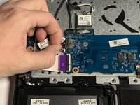
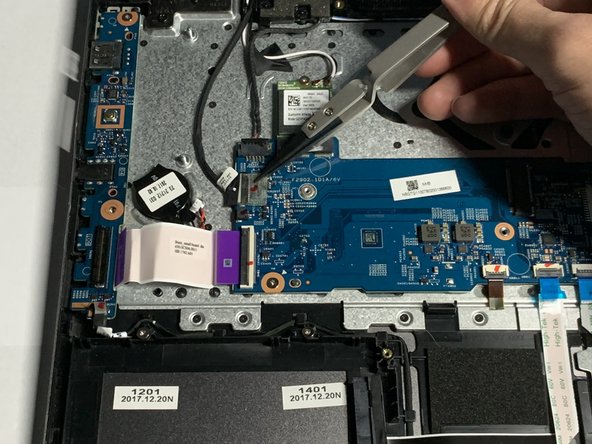
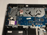
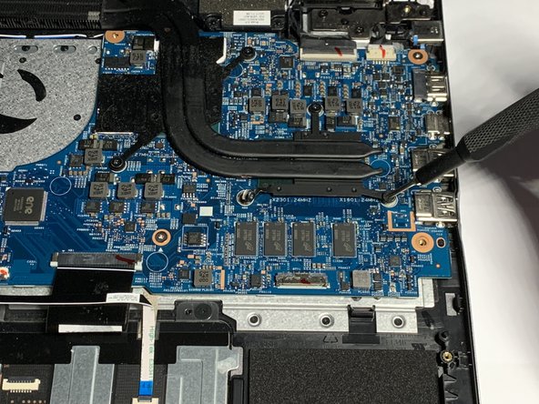
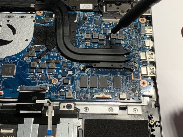
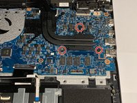
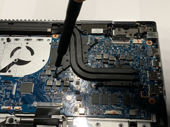
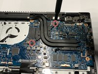
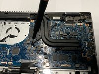
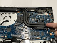
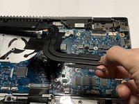
Remove the three 3.5mm screws that secure the heatsink using a Phillips #00 screwdriver (PH00 bit).
-
-
-
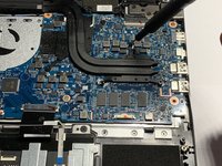
Remove the two 3.5mm screws that secure the heatsink using a Phillips #00 screwdriver (PH00 bit).
-
-
-
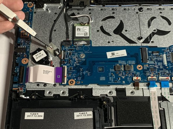
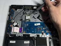
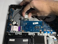
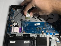
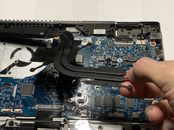
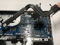
Lift the heat-sink unit upwards and remove it from motherboard.
-
-
-
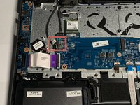
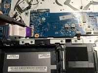
Peel back the tape covering the port.
-
-
-
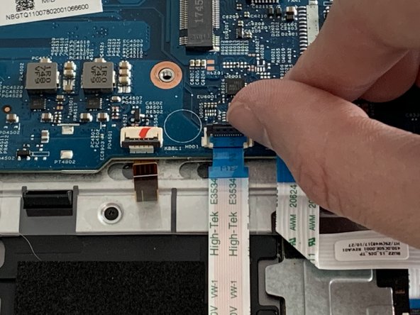
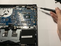
Place your fingernail underneath the black clamp that secures the cable to the ZIF connector.
-
Lift the black clamp upwards to release the cable.
-
Pull the cable away from the motherboard.
-
-
-
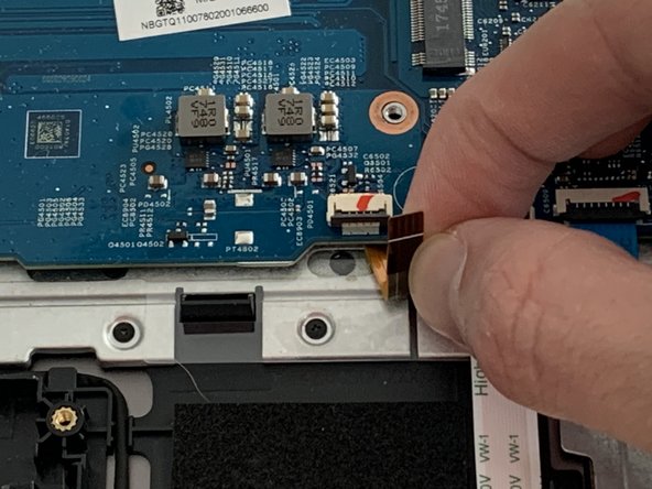
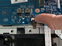
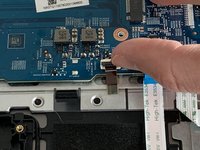
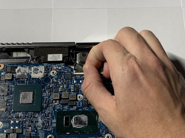
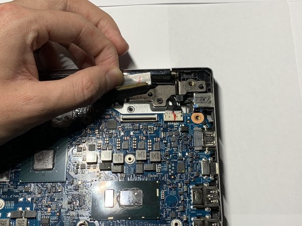
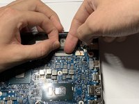
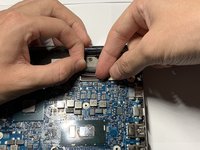
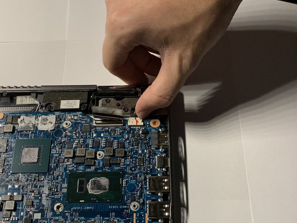
Grip the cable on either side with your fingertips and gently pull away from the port.
-
-
-
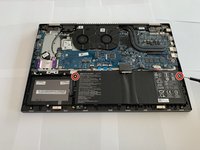
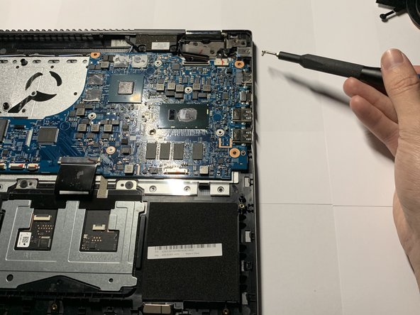
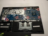
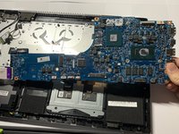
Remove the six 3.5mm screws that secure the motherboard to the laptop using a Phillips #00 screwdriver (PH00 bit).
-
-
-
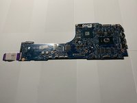
Remove the motherboard from the laptop.
-


To reassemble your device, follow these instructions in reverse order.
To reassemble your device, follow these instructions in reverse order.
crwdns2935221:0crwdne2935221:0
crwdns2935227:0crwdne2935227:0
crwdns2915084:0crwdne2915084:0

Embry-Riddle Aeronautical University, Team S3-G4, Watkins Spring 2020 crwdns2935289:0Embry-Riddle Aeronautical University, Team S3-G4, Watkins Spring 2020crwdne2935289:0
ERAU-WATKINS-S20S3G4
crwdns2931471:04crwdne2931471:0
crwdns2935297:06crwdne2935297:0