crwdns2915892:0crwdne2915892:0
If your laptop is sluggish or you get error codes related to your RAM, it may be time to replace it or upgrade. This guide will walk you through the replacement of your Random Access Memory.
crwdns2942213:0crwdne2942213:0
-
-
Power down the laptop prior to beginning.
-
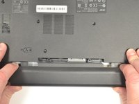
Turn the laptop over with the battery closest to your body.
-
-
-
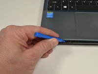
Insert the pointed end of a spudger into the battery release.
-
Slide the release gently all the way to the left.
-
-
-
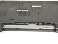
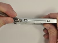
Place your hands on each end of the battery.
-
Pull the battery towards your body to remove it.
-
-
-
Using a #0 Phillips screwdriver, remove a total of eighteen identical 8mm Phillips screws and set them aside.
-
-
-
Rotate the laptop 180 degrees so that the battery compartment is now furthest away from your body.
-
-
-
Turn the laptop over so that you can easily open the screen to a vertical position.
-
-
-
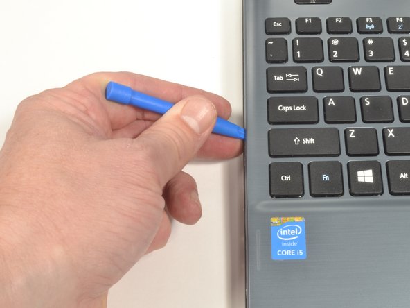
Put your fingers under the top of the keyboard assembly directly below the Acer logo.
-
Carefully pull up on the center until you hear the tabs disengage from the bottom.
-
-
-
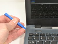
Work your way around the seam with the plastic opening tool carefully prying the base and top cover apart.
-
-
-
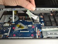
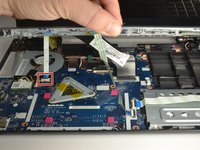
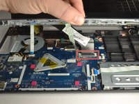
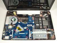
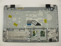
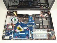
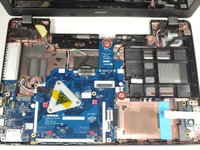
When the two halves are separated, carefully lift up the front of the keyboard and touchpad assembly.
-
You will see three ribbon cables attached to the motherboard.
-
-
-
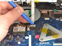
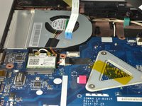
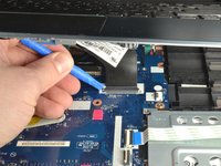
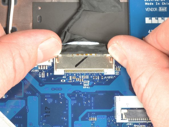
Closest to the ribbon cable on the zero insertion force (ZIF) connector is a white locking tab.
-
Carefully lift up on the locking tab with the plastic opening tool to release the ribbon cable. (Picture 2)
-
Remove the ribbon cable from the connector.
-
-
-
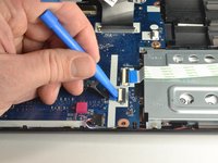
Closest to the ribbon cable on the ZIF connector is a black locking tab.
-
Carefully lift up on the locking tab with the plastic opening tool to release the ribbon cable. (Picture 2)
-
Remove the ribbon cable from the connector.
-
-
-
-
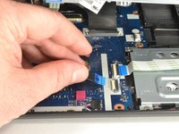
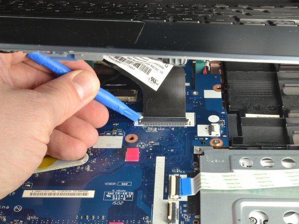
On each side of the large connector there are two white tabs.
-
Carefully push away from you with the plastic opening tool on each white tab to release the cable. (Picture 2)
-
Remove the ribbon cable from the connector.
-
-
-
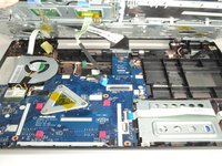
Once all three ribbon cables are disconnected, lift off the top cover with the keyboard and touchpad.
-
-
crwdns2935267:0crwdne2935267:0Tweezers$4.99
-
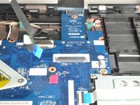
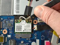
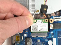
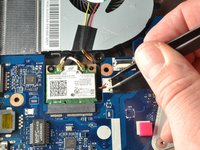
Locate the Wi-Fi card. It is just below the fan and has a white coaxial cable and a black coaxial cable attached to it.
-
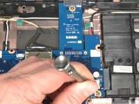
Grab the section of the white coaxial cable behind the brass connection using ESD safe blunt nose metal tweezers.
-
Carefully lift the white and black coaxial cables up and forward to disconnect the them from the Wi-Fi card.
-
-
-
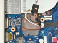
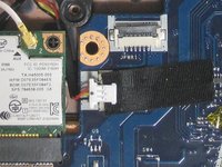
Use a Phillips #0 screwdriver to remove the 3 mm screw from the upper left corner of the Wi-Fi card.
-
-
-
Grab the upper left corner of the Wi-Fi card with your fingers.
-
Gently pull the Wi-Fi card away from the socket.
-
-
-
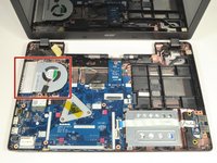
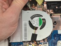
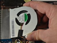
Locate the CPU cooling fan in the upper left corner of the laptop.
-
Using a Phillips #0 screwdriver, remove the two 4.5 mm screws that secure the fan to the case.
-
-
crwdns2935267:0crwdne2935267:0Tweezers$4.99
-
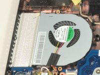
Place the tips of the ESD safe pointed tweezers between the plug and the socket of the fan connection.
-
Gently push the tweezers to the left to disconnect the fan plug.
-
Move the fan connector and its wires to free them from the motherboard and the Wi-Fi card.
-
-
-
Lift the curved end of the fan by about 30 degrees.
-
Use your hand to lift the fan up and to the right until it is clear of the case.
-
-
-
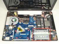
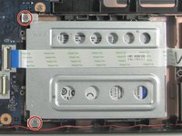
Locate the hard drive and its carriage at the lower right corner of the laptop.
-
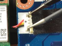
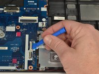
Release the USB port ribbon cable by using the plastic opening tool to carefully lift up the black locking tab of the ZIF connector.
-
Move the USB port ribbon cable to the side.
-
-
-
Use a Phillips #0 screwdriver to remove the two 4 mm screws securing the hard drive carriage in place.
-
-
-
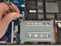
Hold the right side of the laptop in place with your right hand.
-
Put the fingers of your left hand along the top edge of the hard drive carriage.
-
Push the hard drive carriage towards your right hand to disconnect it from the motherboard.
-
-
-
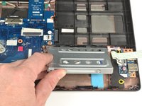
Lift up the hard drive carriage on the edge closest to your body to remove it.
-
-
-
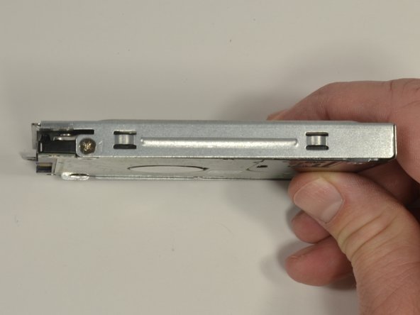
Hold the hard drive carriage with your non-dominant hand along one side. Ensure one of the Phillips screws is visible.
-
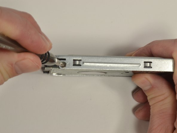
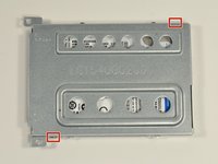
Using a Phillips #0 screwdriver, remove the 3 mm screw to release the side of the hard drive from the carriage.
-
Repeat the previous bullet to remove the second 3 mm Phillips #0 screw.
-
-
-
Use a Phillips #0 screwdriver to remove the two 4 mm screws.
-
-
crwdns2935267:0crwdne2935267:0Tweezers$4.99
-
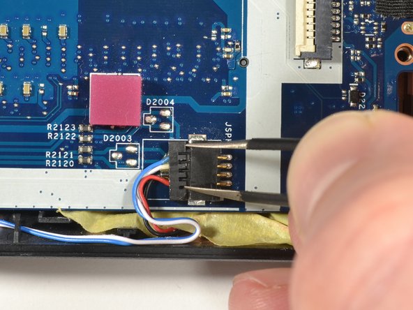
Place the tips of the ESD safe pointed tweezers between the plug and the socket of the speaker connection.
-
Gently push left to disconnect the speaker plug.
-
-
-
Place your fingernails on each side of the screen connection plug. Gently push away from your body to disconnect the plug.
-
-
-
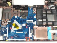
Carefully lift up on the right edge of the motherboard near the hard drive connector.
-
With minimal force, pull the motherboard to the right freeing the ports on the left from the case.
-
Put down the right side and allow the motherboard to rest in the case.
-
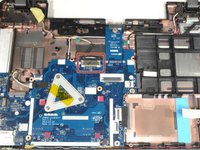
Lift the left side of the motherboard up and turn it over so the ports are now facing right.
-
-
-
Grip the edge of the motherboard closest to your body with your non-dominant hand.
-
Grip the power connection wires with your dominant hand and gently pull away from your body to disconnect.
-
-
-
Lift the motherboard out of the case.
-
-
-
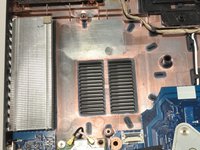
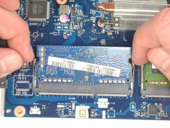
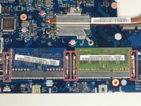
The RAM modules are on the underside of the motherboard at the lower edge.
-
-
-
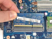
There are two clips holding each RAM module into its respective connector.
-
Use your fingernails to gently pull each set of clips away from the RAM module at the same time.
-
When disengaged, the RAM module will pop up slightly.
-
Repeat this procedure for the remaining RAM module.
-
-
-
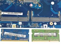
Grip the upper left corner of the RAM module with your fingers.
-
Pull the module away from your body at a slight incline to remove it from the connector.
-
Repeat this procedure for the remaining RAM module.
-


To reassemble your device, follow these instructions in reverse order.
To reassemble your device, follow these instructions in reverse order.
crwdns2935221:0crwdne2935221:0
crwdns2935229:06crwdne2935229:0

crwdns2915084:0crwdne2915084:0

UMass Dartmouth, Team S3-G8, Bailey Fall 2017 crwdns2935289:0UMass Dartmouth, Team S3-G8, Bailey Fall 2017crwdne2935289:0
UMASSD-BAILEY-F17S3G8
crwdns2931471:03crwdne2931471:0
crwdns2935297:08crwdne2935297:0
crwdns2947412:02crwdne2947412:0
Not considering that a laptop would ever come without access to the drive and the RAM, I bought upgrades for both in my Acer Aspire E5-571. In the days before they arrived I researched and was SHOCKED at what I would have to do to install them. So I bought the tools recommended from iFixit, printed out the guide pdf and got to work. It was tough, especially reconnecting the ribbons. But I took my time and got it done right. Took the better part of 3 hours. T'was a miracle my ham fists didn't break anything. Were it not for this guide and the iFixit tools (and a photo lupe and tweezers!) I could have never done this. I would've taken it to Geek Squad and probably been charged 200 bucks or more just for labor. Thanks Aaron and ifixit.
I followed the ram upgrade guide to upgrade to 16gb ram. After I turn on my laptop, nothing comes on the screen, not even the acer logo. The power led is on for some time and goes off. Is there a fix for this? Really need some help here.