crwdns2915892:0crwdne2915892:0
This guide will show how to replace the motherboard if it becomes damaged or non-functional.
crwdns2942213:0crwdne2942213:0
-
-
Use the pointed end of the spudger to slide the battery lock until the battery pops loose.
-
-
-
Slide the battery out of the battery slot.
-
-
-
Unscrew the two RAM 6mm cover screws.
-
Use a PH1 screw bit.
-
-
-
Pop the RAM cover off.
-
Use the plastic opening tool.
-
-
-
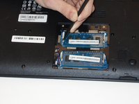
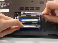
Use either the spudger or your fingers to pinch the clips away from the RAM chip on either side of each chip.
-
The chip should pop up.
-
Slide the RAM memory chips out of the slots.
-
-
-
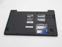
Remove the two 6mm PH1 screws from the bottom of the laptop.
-
-
-
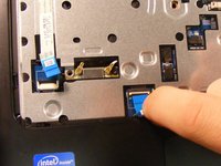
Use the spudger, push the two tabs, located in the battery slot, through their slots to release the keyboard.
-
Do this with the computer slightly open for ease.
-
-
-
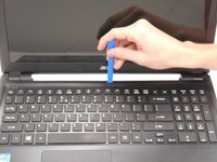
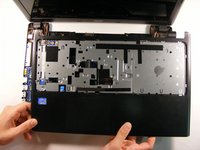
Open the laptop.
-
Start top of the keyboard and use the opening tool to pop the remaining tabs around the keyboard loose.
-
The keyboard can be flipped onto its face once removed.
-
-
-
Use the spudger and slide the grey tabs on either side of the keyboard wires away from the white plastic.
-
-
-
-
Disconnect the keyboard by pulling the blue tape on the wire strip.
-
-
-
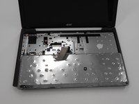
Remove the five 6mm PH1 screws beneath the keyboard.
-
-
-
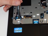
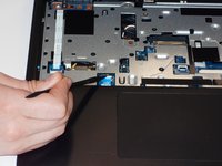
Use the spudger to pop the gray tab up and away from the far left wire strip.
-
Disconnect the wire strip by pulling the blue tab loose.
-
-
-
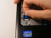
Use the spudger to pop the white tab up away from the wire strip located at the top left corner of the mouse pad.
-
Disconnect the wire strip by pulling the blue tab.
-
-
-
Close the laptop.
-
Remove the remaining 18 6mm PH1 screws from the bottom cover of the laptop.
-
-
-
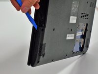
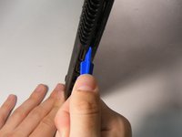
Use the opening tool to separate the back of the laptop from the inside cover.
-
Open the computer and remove the inside cover.
-
-
-
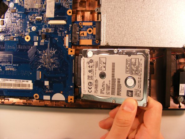
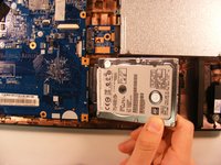
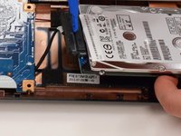
Lift the HDD out of the base and use the opening tool to disconnect the HDD from the motherboard wire.
-
-
-
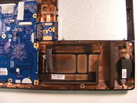
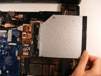
Slide the optical disc drive out of the slot to disconnect it from the motherboard.
-
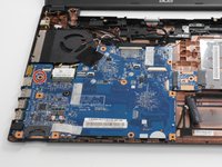
Unscrew the main 3.5mm PH1 screw from the motherboard.
-
-
-
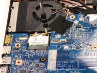
Unscrew the 3.5mm PH1 screw from the Wireless Lan chip.
-
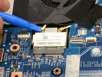
Use the opening tool to pop both wires off of the Wireless Lan chip.
-
Pull the Wirelss Lan Chip to remove it from the motherboard.
-
-
-
Pull the tape covering the wires for the Wireless Lan chip up.
-
Pull the black and white wires loose.
-
-
-
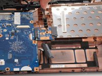
Pull up the tape securing the optical wires to the motherboard.
-
Disconnect the wire plug-in from the motherboard.
-
-
-
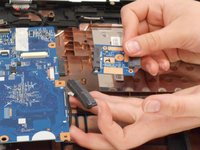
Unscrew the 3.5mm PH1 screw securing the optical disk drive to motherboard connector.
-
Pull the connector to disconnect it from the motherboard.
-
-
-
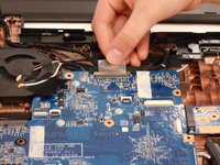
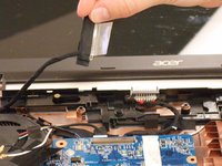
Flip the motherboard up towards the screen to access the underside.
-
-
-
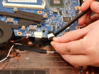
Use the spudger to disconnect the remaining three wires from the motherboard.
-
Once the wires are disconnected, the motherboard is completely disconnected from the laptop frame.
-
-
-
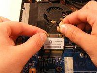
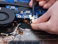
Unscrew the three PH1 screws connecting the CPU fan to the motherboard.
-
-
-
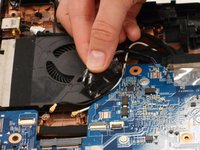
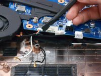
On the side opposite the CPU fan screws, pull loose the tape securing the fan assembly to the motherboard.
-
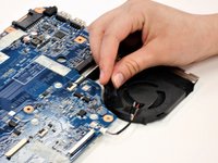
The CPU fan can now be separated from the motherboard.
-
-
-
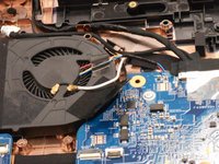
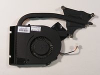
The motherboard can be replaced once disconnected from the CPU cooling fan.
-


To reassemble your device, follow these instructions in reverse order.
To reassemble your device, follow these instructions in reverse order.
crwdns2935221:0crwdne2935221:0
crwdns2935227:0crwdne2935227:0
crwdns2915084:0crwdne2915084:0

University of Alabama, Team S2-G7, Bedsole Spring 2018 crwdns2935289:0University of Alabama, Team S2-G7, Bedsole Spring 2018crwdne2935289:0
UA-BEDSOLE-S18S2G7
crwdns2931471:03crwdne2931471:0
crwdns2935297:012crwdne2935297:0