crwdns2915892:0crwdne2915892:0
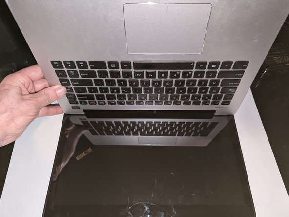
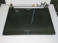
There are new keyboard-only replacement parts for sale, but using them requires melting off or otherwise removing the head of several plastic retaining pins, then figuring out how to re-secure them. That kind of replacement is beyond the scope of this guide, so we'll only be dealing with a replacement that comes with a keyboard + palm rest as a single unit as pictured above.
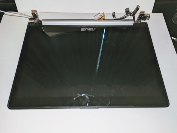
Outside of a malfunctioning keyboard, there are other possible reasons to replace this part. The palm rest is the foundation that all other components are mounted on, so there are many sources of damage possible. In the case of this particular repair, the mounting nuts for the hinges had been broken off, making it impossible to secure the display to the chassis.
crwdns2942213:0crwdne2942213:0
-
-
Flip the device over and remove the ten 5.7 mm screws with a Phillips #0 screwdriver.
-
-
-
Use a spudger or your fingers to go around and lift the edges and release the back panel.
-
-
-
Using a spudger, lift up the plug connecting the battery to the motherboard.
-
-
-
With a Phillips #0 screwdriver, remove the four 5.7 mm screws holding the battery to the laptop.
-
-
-
Carefully lift the battery up and out of the device.
-
-
-
Remove the three Phillips #0 screws holding the the hard drive in place:
-
Two 3.8 mm screws.
-
One 5.7 mm screw.
-
-
-
Pull left and lift out the hard drive.
-
-
-
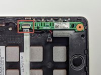
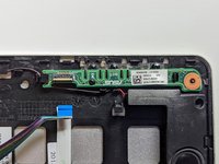
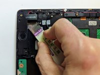
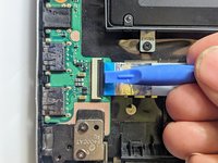
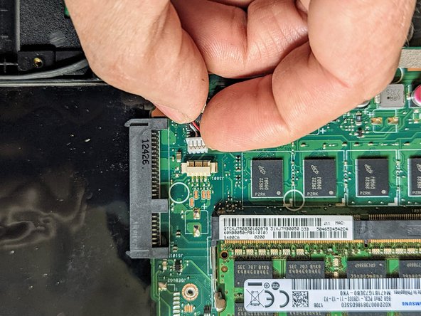
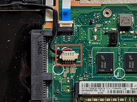
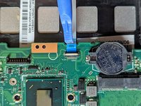
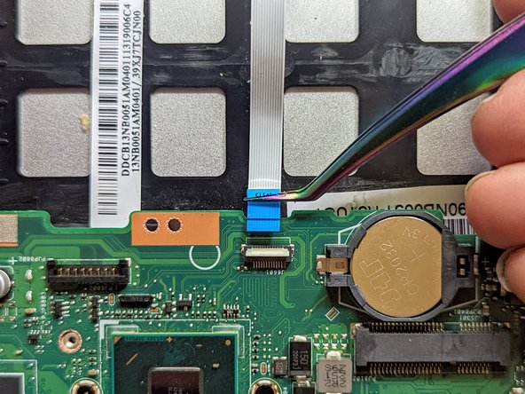
Disconnect the ribbon cable connecting the LED daughterboard and the motherboard by lifting the white tab on the LED side of the cable.
-
-
-
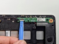
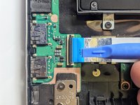
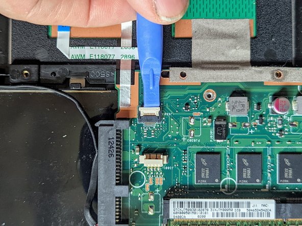
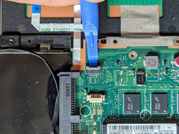
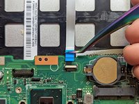
Pull out the ribbon cable on the LED side by pulling on the blue tab.
-
-
-
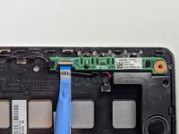
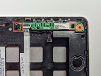
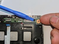
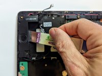
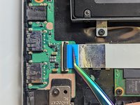
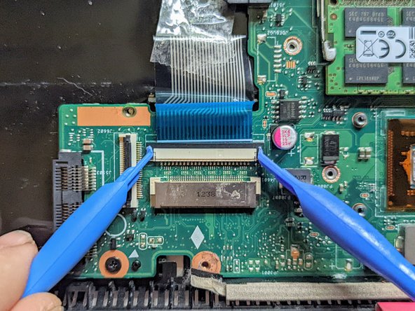
The LED board is held in place by a hook on the left end and a latch on the right.
-
Press the latch with a spudger while lifting with a fingernail.
-
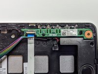
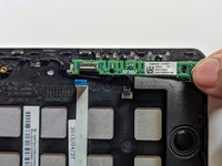
Pull the LED board to the right to clear the left-hand hook.
-
-
-
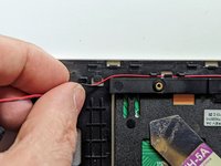
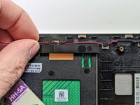
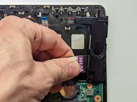
Pull out the black cable connecting the motherboard to the speakers.
-
-
-
Deroute the speaker wire from the motherboard to the left speaker.
-
-
-
Using a metal opening tool, pry off the left speaker.
-
-
-
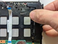
Deroute the wires from the left speaker to the right.
-
-
-
Continue to deroute the speaker wire to the right speaker.
-
-
-
Using a metal opening tool, pry off the right speaker.
-
-
-
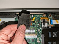
Remove the black shield covering the display connector and the heat sink.
-
-
-
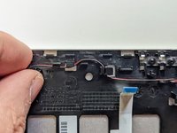
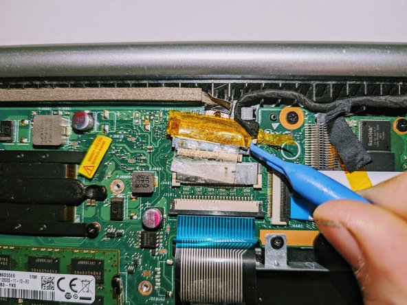
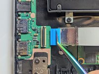
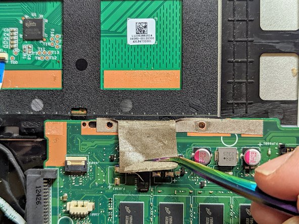
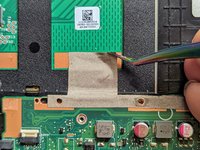
Remove the black tape securing the keyboard ribbon cable to the display connector.
-
Fold the ribbon cable the opposite way, resecuring it to the hard drive to keep it out of the way.
-
-
-
-
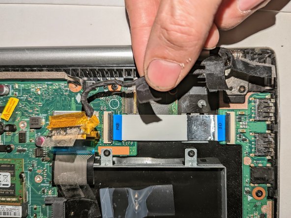
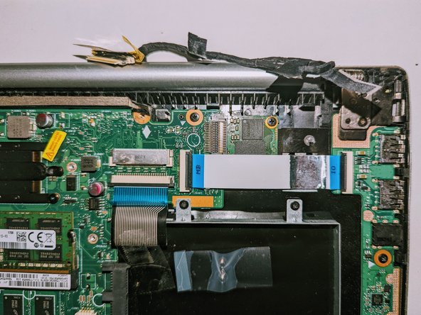
Peel off the clear tape from the motherboard display connector.
-
-
-
Position spudgers on the white tabs on either side of the connector and push evenly to unplug the display.
-
-
-
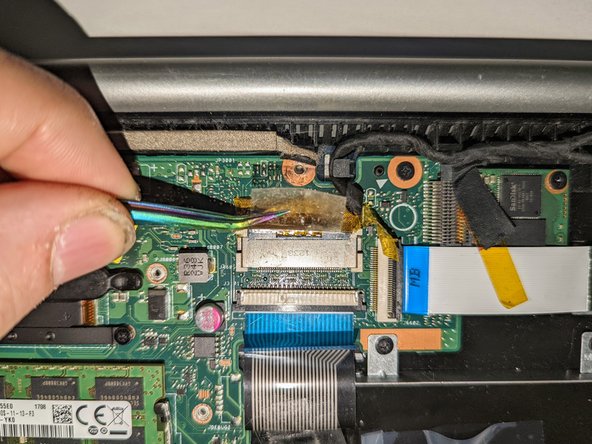
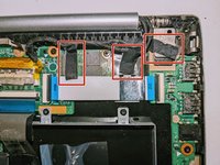
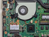
Peel off the three pieces of black tape securing the display cable to the motherboard.
-
Deroute the cable from the channel it sits in.
-
Move the cable to the side, out of the way.
-
-
-
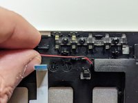
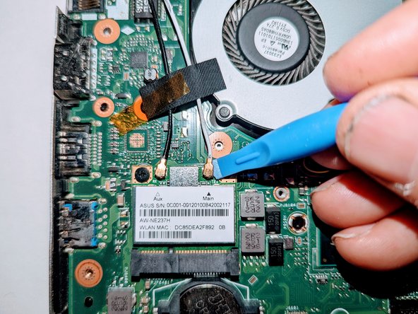
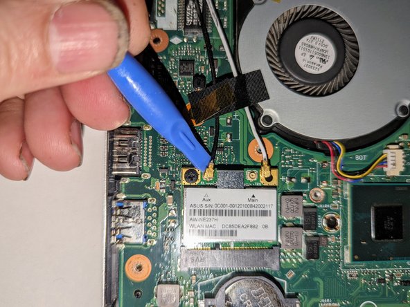
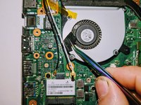
Use a spudger to release the cables from the wifi card.
-
-
-
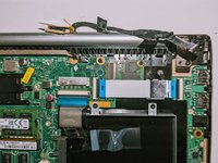
Lift the tapes securing the wires to the motherboard.
-
Move the wires to the side out of the way.
-
-
-
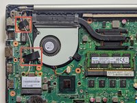
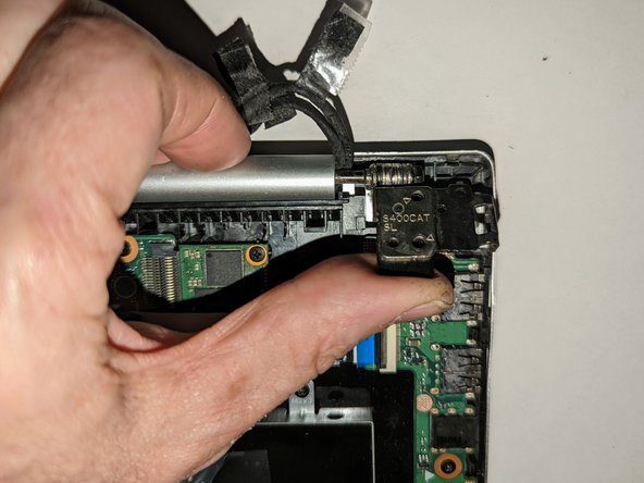
Remove the two screws securing the hinge on the left.
-
Pry the hinge up by hand to a 90 degree angle.
-
-
-
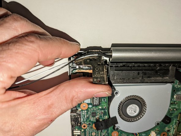
Remove the two screws securing the hinge on the right.
-
Pry the hinge up by hand to a 90 degree angle.
-
-
-
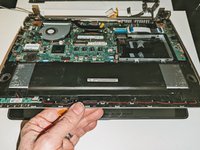
Lift the base of the laptop from the front.
-
Raise it to a 90 degree angle.
-
Slide it forward slightly to clear the hinges.
-
The display is now free.
-
-
-
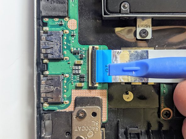
Flip up the retaining latch on the I/O board ribbon cable.
-
-
-
Pull the cable straight out of the connector by the blue tab.
-
-
-
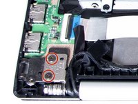
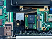
Remove the two screws securing the left hinge to the I/O board.
-
Pry the hinge up by hand to a 90 degree angle.
-
-
-
Lift the board on the ribbon cable side far enough to clear the guide pin(s) then pull it back away from the side of the case.
-
-
-
Disconnect the I/O Board ribbon cable from the motherboard.
-
Flip up the retaining latch with a spudger.
-
-
-
Grasp the ribbon cable by the blue tab and pull it straight out from the connector.
-
-
-
Disconnect the I/O Board ribbon cable from the I/O board.
-
Flip up the latch with a spudger.
-
-
-
Grasp the ribbon cable by the blue tab and pull it straight out from the connector.
-
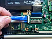
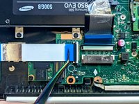
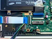
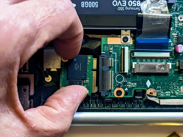
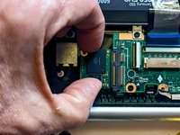
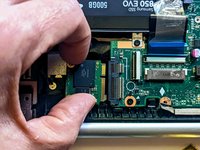
Remove the ribbon cable to expose the SSD device.
-
-
-
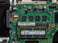
Grasp the SSD by the sides and slide it out of the connector.
-
-
-
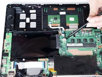
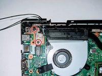
Remove the screw securing the fan to the palm rest. All other fan and heatsink screws can remain in place.
-
-
-
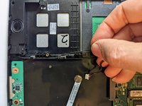
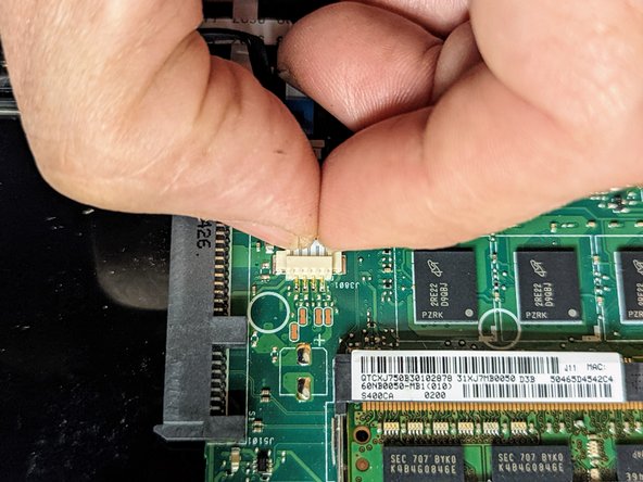
Unplug the black cable connecting the motherboard to the speakers.
-
-
-
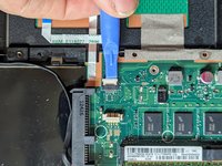
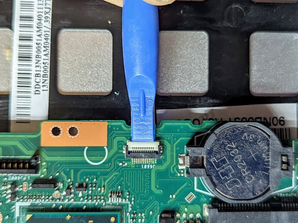
Flip up the trackpad ribbon cable retainer with a spudger.
-
-
-
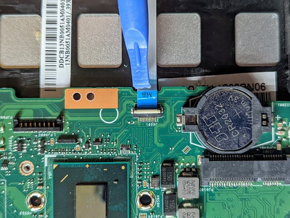
Pull the cable straight out from the connector.
-
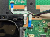
Peel the trackpad cable off the conductive tape strip below it.
-
-
-
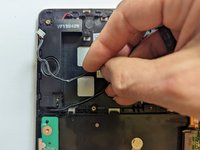
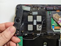
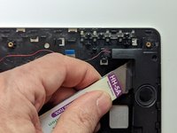
Remove the first of the two conductive tapes grounding the trackpad.
-
-
-
Remove the second conductive tape grounding the trackpad.
-
-
-
Use a spudger to flip up the LED board cable retainer.
-
-
-
Pull the ribbon cable straight out from the connector.
-
-
-
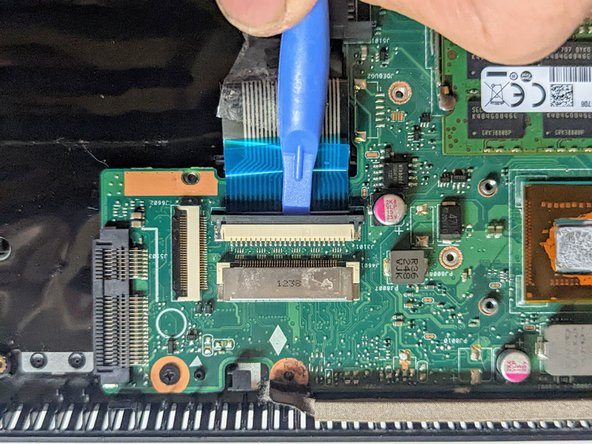
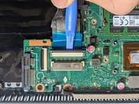
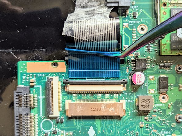
Place a spudger on the ears on either side of the keyboard ribbon cable connector and push evenly on both sides to release it.
-
Lift it slightly to relieve the tension.
-
-
-
Remove the two mounting screws.
-
-
-
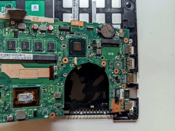
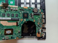
Lift and slide the motherboard toward the hard drive to clear the connectors on the opposite side from the case.
-
-
-
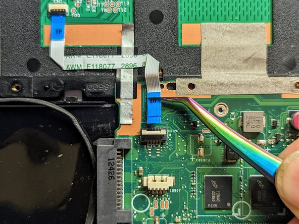
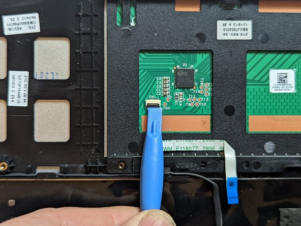
Flip the retaining latch on the trackpad ribbon cable connector up with a spudger.
-
-
crwdns2935267:0crwdne2935267:0Tweezers$4.99
-
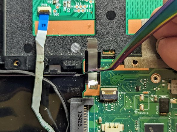
Grasp the blue tab with fine tip tweezers and pull the cable straight out from the connector.
-
Gently peel the trackpad ribbon cable off the trackpad.
-
-
-
Lift the side of the trackpad farthest from the side of the case and slide it away from the edge to remove it.
-
-
-
The keyboard / palm rest has now been completely disassembled.
-


To reassemble your device, follow these instructions in reverse order to install your parts onto your replacement assembly.
To reassemble your device, follow these instructions in reverse order to install your parts onto your replacement assembly.
