crwdns2915892:0crwdne2915892:0
Sometimes screens stop working. This guide will show you how to replace your screen and get back to browsing.
crwdns2942213:0crwdne2942213:0
-
-
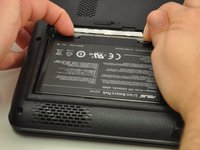
Slide the tab over to unlock the battery cover located on the bottom-left corner of the laptop.
-
-
-
Lift the exposed lip and remove the battery cover.
-
-
-
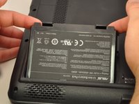
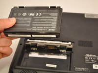
Press the tabs on the battery and lift them. The battery should come out easily.
-
-
-
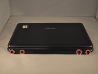
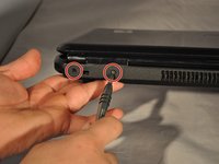
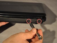
Using the PH1 screwdriver, remove the four 4 .75 mm screws that are located on the vent panel.
-
-
-
Remove the one .5 mm screw located in the top right corner of the battery compartment.
-
-
-
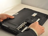
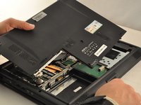
Remove the bottom panel by sliding it toward the hinges and lifting the back panel up.
-
-
-
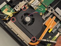
Unplug the wire cable attached to the fan by pulling it out .
-
-
-
Using the PH1 screwdriver, remove the 3 .75mm screws labeled as 1, 2, and 3 on the fan. NOTE these screws have the labels "1", "2", and "3" next to them.
-
Lift the fan up with your fingers.
-
-
-
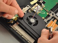
Using the PH1 screwdriver remove the two .75 mm screws from the hinge side of the laptop.
-
-
-
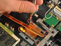
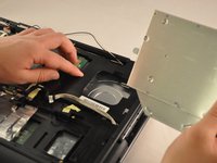
Using the PH1 screwdriver, remove the four .75 mm screws from the copper heat sync. They will be labeled 1-4.
-
Pull the copper heat sync out of the laptop.
-
-
-
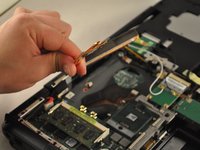
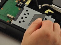
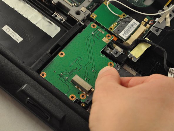
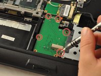
Using the PH1 screwdriver, remove four .75 mm screws from the driver, located in the bottom-right corner of the laptop.
-
-
-
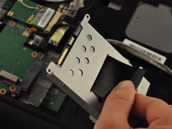
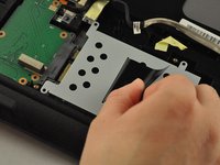
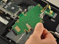
Pull on the black tab on the driver to slide the driver back, and lift the driver out of the laptop.
-
-
-
Using the PH1 screwdriver, remove the five .5 mm screws from the SD card reader, located in the bottom-middle corner of the laptop.
-
Slide the SD card reader away and out.
-
-
-
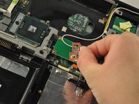
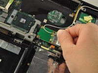
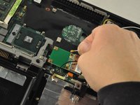
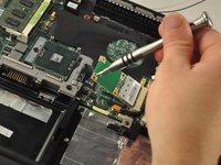
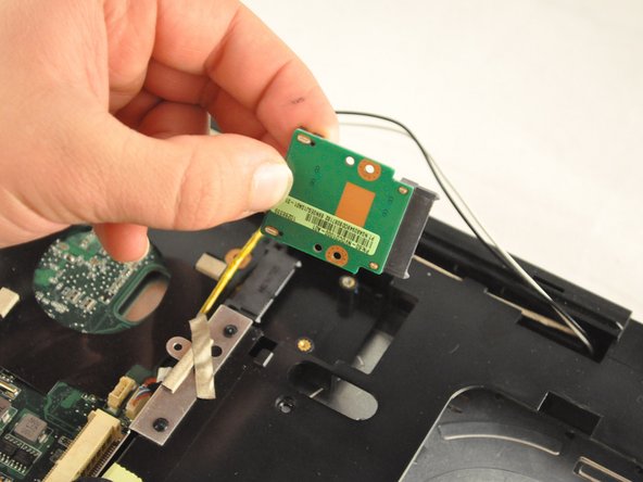
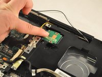
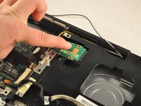
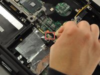
Detach the white and black wires from the Wi-Fi card, located in the central area of the laptop.
-
-
-
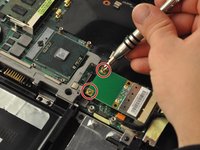
Using the PH 1 screwdriver, remove the two .25 mm screws from the Wi-Fi card.
-
-
-
-
Slide the Wi-Fi card out of its slot to remove.
-
-
-
Using the PH1mm screwdriver, remove one .5 mm screw from the disk drive, located inthe top-right corner of the laptop.
-
-
-
Slide the disc drive out of its slot.
-
-
-
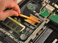
Using the PH 1 screwdriver, remove the two .5 mm screws from the RAM drive.
-
-
-
Slide and lift the RAMdrive out of its port.
-
-
-
Using the PH1 screwdriver, remove the .75 mm screw from the plastic housing corner, located in the bottom-right corner of the laptop.
-
-
-
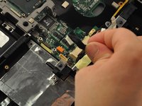
Unplug the black cable from the central area of the laptop.
-
-
-
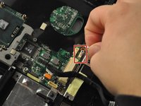
Unplug the wire cable in the central area of the laptop.
-
-
-
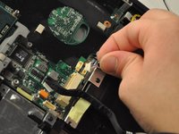
Unplug the wire and black cables on the motherboard, located in the upper-left corner of the laptop.
-
-
-
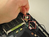
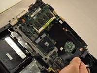
Using the PH1 screwdriver, unscrew the two .75 mm screws from the top-left corner of the motherboard.
-
-
-
Using the PH 1 screwdriver, remove the .75 cm screw from the top-middle section of the motherboard.
-
-
-
Using the PH1 screwdriver, remove the .75 mm screw from the top-middle corner of the motherboard.
-
-
-
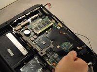
Using the PH1 screwdriver, remove the three .75 mm screws from the bottom corner of the motherboard.
-
-
-
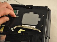
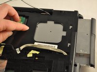
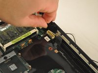
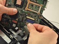
Slide the motherboard to the right and lift it up, but do not pull it completely out.
Motherboard has THREE cables attached to the face — 2 Ribbon and 1 Modular
-
-
-
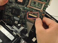
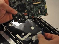
Gently unplug the ribbon cable from the underside of the motherboard.
-
-
-
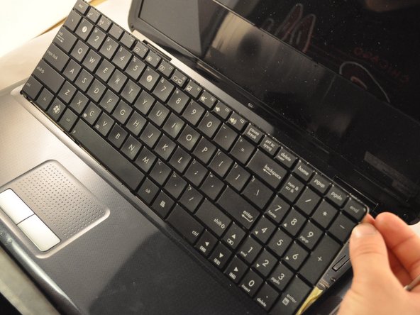
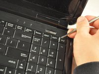
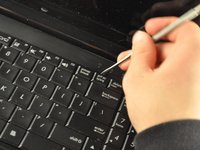
Use the metal spudger or opening tool across the top edge of the keyboard to pop it out.
-
-
-
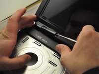
Use the metal spudger or opening tool to pop out the plastic hinge covers.
-
-
-
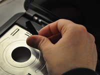
Use the PH1 screwdriver to remove the .75 mm screws from the hinges. Each hinge has one screw.
-
-
-
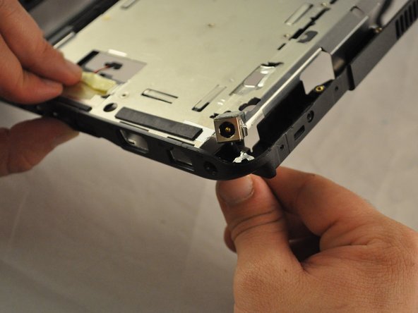
The screen should separate from the rest of the laptop.
-
-
-
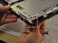
Using the PH1 screwdriver, remove the .75 mm screw from the bottom-middle section was previously covering.
-
-
-
Using the PH 1 screwdriver, remove the .75 cm screw from the bottom-middle section where the keyboard was previously covering.
-
-
-
Lift the front cover off of the laptop.
-
-
-
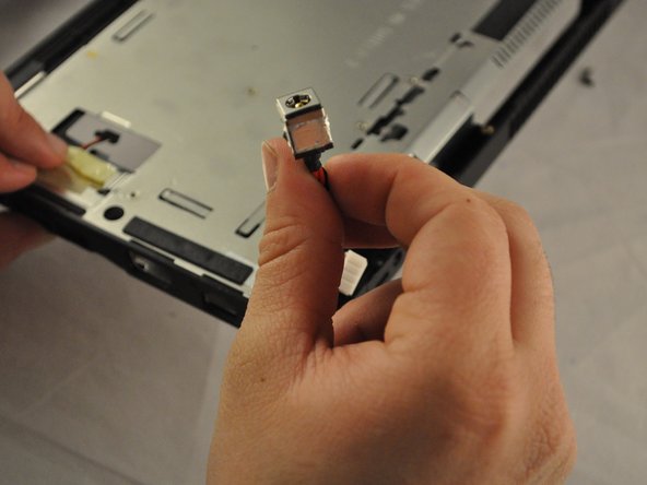
Flip the laptop back over. The charging port will be located in the top-right corner.
Step 30 — there are THREE cables (2 ribbon and 1 modular) attached to the face of the motherboard that you cannot see until it’s been removed.
Yes indeed, thanks Scot.
Also this guide forgets to remove all the screws around the outside edge, to remove the top cover Step 37. 7 screws by my count. 4 on I/O side, 3 on DVD side
Also Step 33 removing hinges, requires the pictured screw on top of each, as well as 2 underneath each hinge
-
-
-
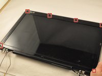
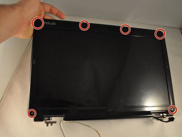
Using a metal spudger, pop off the six rubber screw covers.
-
-
-
Using the PH1mm screwdriver, remove the six .75 mm screws from the front of the screen frame.
-
-
-
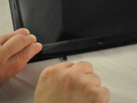
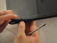
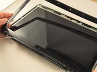
Use the plastic opening tool or spudger along the edge of the frame, to pry off the frame.
-
-
-
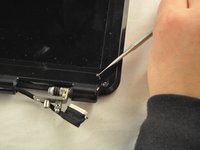
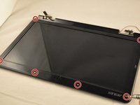
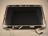
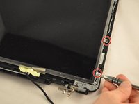
Using the PH1 screwdriver, remove the four bottom .75 mm screws from the screen frame.
-
-
-
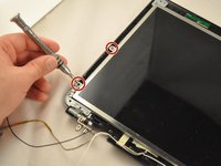
Using the PH1 screwdriver, remove the two .75 cm screws from the top of the screen frame.
-
-
-
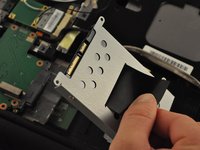
Lift the bracket off the top of the screen frame.
-


To reassemble your device, follow these instructions in reverse order.
To reassemble your device, follow these instructions in reverse order.
crwdns2935221:0crwdne2935221:0
crwdns2935227:0crwdne2935227:0

crwdns2915084:0crwdne2915084:0

Eastern Washington University, Team S1-G3, Carnegie Fall 2017 crwdns2935289:0Eastern Washington University, Team S1-G3, Carnegie Fall 2017crwdne2935289:0
EWU-CARNEGIE-F17S1G3
crwdns2931471:04crwdne2931471:0
crwdns2935297:05crwdne2935297:0
crwdns2947412:03crwdne2947412:0
Very well done. Thank You
Thank you for your time!
Now, I don´t know how to connect the cables to the motherboard because they are too short.